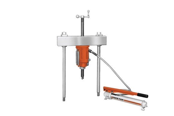
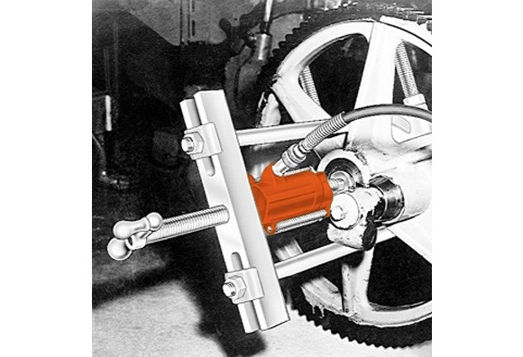
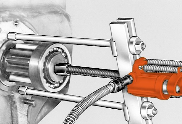
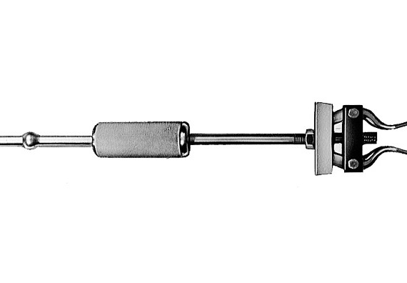
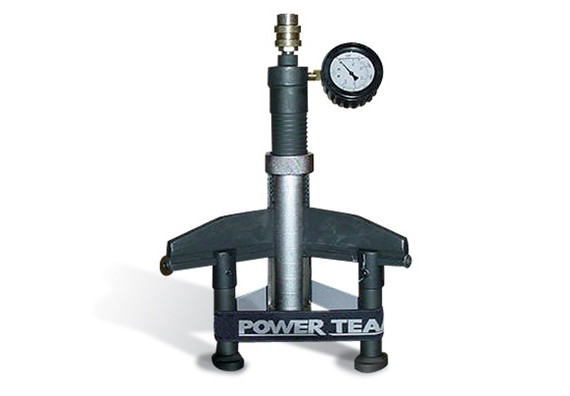
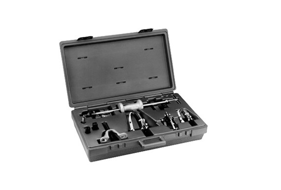
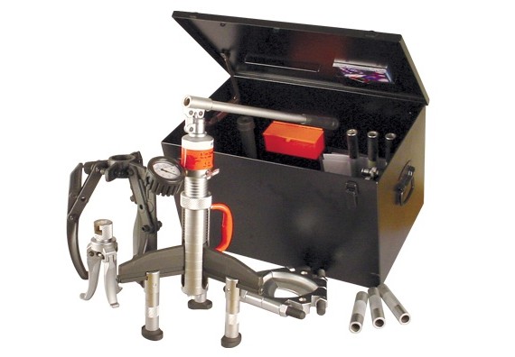
- Can apply a hydraulic pushing or pulling force, depending on how the puller is set up.
- Each unit includes perfectly matched hydraulic components that can be detached from the Push- Puller® for other tasks requiring dependable Power Team power; assuring maximum return on your investment.
- Optional leg kits adapt your Push-Puller® to extra long or extra short reach.
- A wide variety of threaded adapters, bearing pulling attachments and internal pulling attachments can be used in combination with our Push-Pullers®.
Selection and capacity rating – Each Push-Puller’s specified tonnage “capacity†is determined using its standard legs in tension. Using longer legs, or a setup in which the legs are in compression, will reduce the “capacityâ€. Always select the largest “capacity†puller and the shortest legs that will fit the job.
Power Twin® cylinder – This unique center-hole cylinder powers each Push-Puller®. Puller screw runs right between the twin spring cylinder. A basic head allows you to change from a tapped hole to a plain hole by merely changing the head insert.
| Order No. | Cap. (tons) |
Description | Weight (lbs) |
|---|---|---|---|
| 1062 | 17 ½ | Puller only. (Cylinder, pump, hose, coupler, screw, and crank not included). | 20.0 |
| Packages: | |||
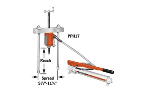
| PPH17 | 17 ½ | Push-Puller® with RT172 center-hole Power Twin® cylinder, cylinder half coupler, P55 pump, 9767 6-ft. poly-urethane hose, 9798 hose half coupler, 16 1/2″ legs, 24827 leg ends, 1″-8 x 20″ lg. adjusting screw (32118) and adjusting crank (24814). | 59.0 |
| PPH17R | 17 ½ | Same as above, but without P55 pump, 9767 6-ft. poly-urethane hose and 9798 hose half coupler. | 40.0 |
USE WITH:
|  Order No. | Description |
|---|---|
| 679 | Pulley Pulling Attachment |
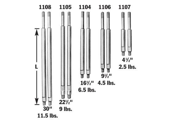
| 1104 | 16 1/2″ Puller Legs |
| 1105 | 22 1/2″ Puller Legs |
| 1106 | 9 1/2″ Puller Legs |
| 1107 | 4 1/2″ Puller Legs |
| 1108 | 30″ Puller Legs |
| 1124 | Bearing Pulling Attachment |
| 1130 | Bearing Pulling Attachment |
| 1154 | Internal Pulling Attachment |
| Pair of puller legs for 17 1/2-ton “capacity†Push-Puller®.
NOTE: L = leg length: 4 1/2″, 9 1/2″, 16 1/2″, 22 1/2″, 30″; subtract 4 7/8″ from leg length to determine reach when using leg end caps. Leg Ends – Upper leg ends are threaded 3/4″-16″ lg. Lower leg ends are threaded 5/8″-18″ lg. |
|
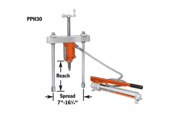
30 Ton Capacity, Push-Puller®:
| Order No. | Cap. (tons) |
Description | Weight (lbs) |
|---|---|---|---|
| 1070 | 30 | Puller only. (Cylinder, pump, hose, coupler, screw and crank not included.) | 42.0 |
| Packages: | |||
| PPH30 | 30 | Push-Puller® with RT302 center-hole Power Twin® cylinder, cylinder half coupler, P55 pump, 9767 6-ft. polyurethane hose, 9798 hose half coupler, 18″ legs (1110), 28390 leg ends, 1 1/4″-7 x 24″ lg. adjusting screw (34758), and adjusting crank (27198). | 102.0 |
| PPH30R | 30 | Same as above, but without P55 pump, 9767 6-ft. polyurethane hose and 9798 hose half coupler. | 82.0 |
USE WITH:
|  Order No. | Description |
|---|---|
| 679 | Pulley Pulling Attachment |
| 680 | Bearing Pulling Attachment (Use two 8012 adapters to connect to puller.) |
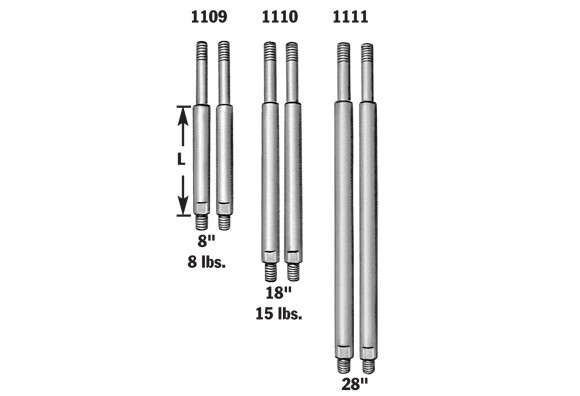
| 1109 | 8″ Puller Legs |
| 1110 | 18″ Puller Legs |
| 1111 | 28″ Puller Legs |
| 1166 | Internal Pulling Attachment |
| Pair of puller legs for 30 ton “capacity†Push-Puller®.
NOTE: L = leg length: 8″, 18″, 28″; subtract 5 7/8″ from leg length to determine reach when using leg end caps. Leg Ends are threaded 1″-14 x 1 1/4″ lg. |
|
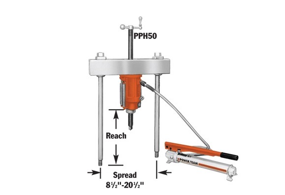
50 Ton Capacity, Push-Puller®:
| Order No. | Cap. (tons) |
Description | Weight (lbs) |
|---|---|---|---|
| 1076 | 50 | Puller only. (Cylinder, pump, hose, coupler, screw and crank not included.) | 106.0 |
| Packages: | |||
| PPH50 | 50 | Push-Puller® with RT503 center-hole Power Twin® cylinder, cylinder half coupler, P55 pump, 9767 6-ft. polyurethane hose, 9798 hose half coupler, 24″ legs (1112), 1 5/8″-5 1/2 x 30 3/8″ lg. adjusting screw (32698), and adjusting crank (29595). | 201.0 |
| PPH50R | 50 | Same as above, but without P55 pump, 9767 6-ft. polyurethane hose and 9798 hose half coupler. | 181.0 |
USE WITH:
|  Order No. | Description |
|---|---|
| 1112 | 24″ Puller Legs |
| 1113 | 34″ Puller Legs |
| 1128 | Bearing Pulling Attachment |
| Pair of puller legs for 50 ton “capacity†Push-Puller®.
Leg Ends are threaded 1 1/4″-12 x 1 3/4″ lg. |
|
 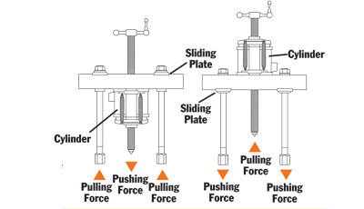
ASSEMBLING THE TOOL TO APPLY PUSHING OR PULLING FORCE:
1. Determine if you want the tool’s forcing screw to push or pull.
2. To exert pushing force, the forcing nut is installed beneath the cross block, as shown on left.
3. To cause the forcing screw to pull, the forcing nut is placed on top of the cross block.
4. The sliding plates must always be placed on the opposite side of the cross block from the forcing nut.
Go to Accessories section for product detail:
Accessories:
| Catalog | |

