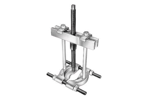
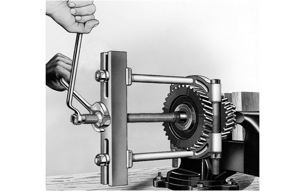
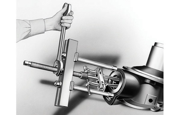
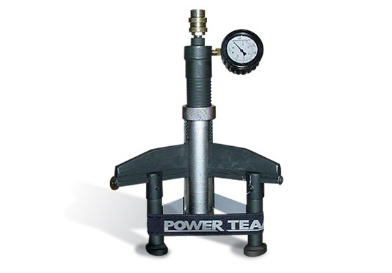
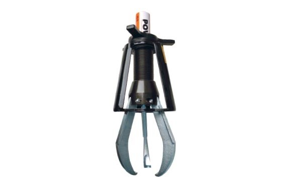
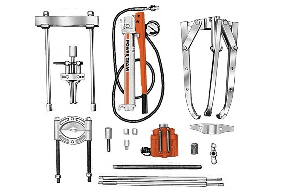
- Can apply a pushing or pulling force, depending on how the puller is set up.
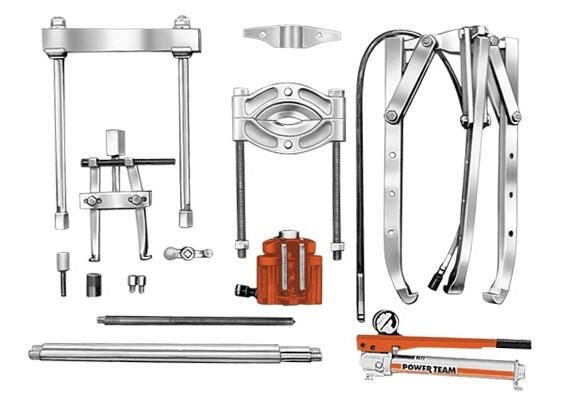
- Optional leg kits adapt your Push-Puller® to extra long or extra short reach.
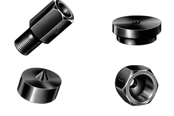
- A wide variety of threaded adapters, bearing pulling attachments and internal pulling attachments can be used in combination with Push Pullers®
Meets Fed. Spec.: GGG-P-00781-D
| Order No. | Cap. (tons) |
Description | Weight (lbs) |
|---|---|---|---|
| 927 | 10 | 10-Ton Capacity can be used with bearing pulling attachment (1123) or pulley pulling attachment (679). May also be used with Nos. 1150, 1151, 1152, or 1153 internal pulling attachments. | 7.0 |
| 938 | 17 ½ | 171â„2-Ton Capacity can be used with bearing pulling attachments (1124 and 1130) or pulley pulling attachments (679 and 680). May also be used with Nos. 1150, 1151, 1153, 1165, or 1166 internal pulling attachments. | 20.0 |
| 939 | 30 | 30-Ton Capacity can be used with bearing pulling attachments (1126 and 1127) or No. 680 pulley pulling attachment (Note: two 8012 adapters are required to connect 680 to puller). Can be used with No. 1165 internal pulling attachment. | 44.0 |
| Â Order No. |
 Cap. (ton) |
 Max. |  Screw | Size | Notes |  Weight (lbs.) |
|
|---|---|---|---|---|---|---|---|
| Reach | Spread | ||||||
| 927 | 10 | 8 1/4″ | 2 1/8″ – 7 1/4″ | 3/4″ – 16 x 12″ | 1/2″ of forcing screw tip end is threaded 5/8″-18. | Legs (1100) and leg ends (24827) included. | 7.0 |
Available Components for 927
| Order No. | Description | Weight (lbs.) |
|---|---|---|
| 1100 | 6 3/4″ Legs | 1.5 |
| 1101 | 15 3/4″ Legs | 3.25 |
| 1102 | 11 3/4″ Legs | 2.25 |
| 1103 | 4 3/4″ Legs | 1.0 |
| Extra Legs (pair) for Push-Puller® (927) (Reach equals leg length plus 1 1/2″ with leg end caps.) |
||
17 ½ Ton Capacity, Mechanical Push-Puller®:
| Â Order No. |
 Cap. (ton) |
 Max. |  Screw | Size | Notes |  Weight (lbs.) |
|
|---|---|---|---|---|---|---|---|
| Reach | Spread | ||||||
| 938 | 17 ½ | 11 1/8″ | 3 1/8″-11 3/4″ | 1″-14×13 1/4″ | Leg ends threaded 5/8″ | Legs (1106) and leg ends (24827) included. | 20.0 |
Available Components for 938
| Order No. | Description | Weight (lbs.) |
|---|---|---|
| 1104 | 16 1/2″ Legs | 6.5 |
| 1105 | 22 1/2″ Legs | 9.0 |
| 1106 | 9 1/2″ Legs | 4.5 |
| 1107 | 4 1/2″ Legs | 2.5 |
| 1108 | 30″ Legs | 11.5 |
| Extra Legs (pair) for Push-Puller® (938) (Reach equals leg length plus 2″ with leg end caps.) |
||
30 Ton Capacity, Mechanical Push-Puller®:
| Â Order No. |
 Cap. (ton) |
 Max. |  Screw | Size | Notes |  Weight (lbs.) |
|
|---|---|---|---|---|---|---|---|
| Reach | Spread | ||||||
| 939 | 30 | 10 1/2″ | 7 -16 1/4″ |
1 1/2″ – 12×17 1/4″ | Leg ends threaded 1″-14. | Legs (1109) and leg ends (28390) included. | 44.0 |
Available Components for 939
| Order No. | Description | Weight (lbs.) |
|---|---|---|
| 1109 | 8″ Legs | 8.0 |
| 1110 | 18″ Legs | 15.0 |
| 1111 | 28″ Legs | 22.0 |
| Extra Legs (pair) for Push-Puller® (939) (Reach equals leg length plus 2 5/8″ with leg end caps.) |
||
 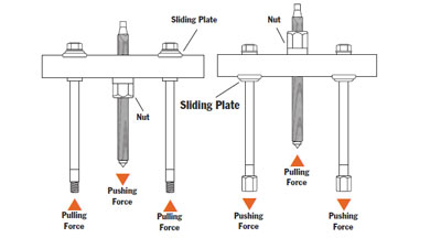
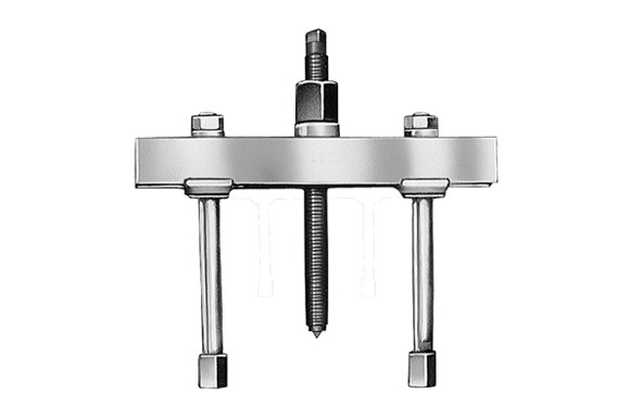
ASSEMBLING THE TOOL TO APPLY PUSHING OR PULLING FORCE:
1. Determine if you want the tool’s forcing screw to push or pull.
2. To exert pushing force, the forcing nut is installed beneath the cross block, as shown on left.
3. To cause the forcing screw to pull, the forcing nut is placed on top of the cross block.
4. The sliding plates must always be placed on the opposite side of the cross block from the forcing nut.
Go to Accessories section for product detail:
Accessories:
| Catalog | |
| Operating Instructions | |

